Welcome to the official website of Nanyang Huaye Explosion-proof Instrument Co., Ltd!
Service Hotline:0377-61613169 | E-mail: abc@huayex.com


Pd series positive pressure purge control system
The Pd type positive pressure purge control system is mainly used to control the ventilation purge pressure inside electrical equipment in hazardous locations.
Classification:
Detailed introduction
一、Overview
The Pd type positive pressure purge control system is mainly used to control the ventilation purge pressure inside electrical equipment in hazardous locations. The purge gas enters the inner cavity of the electrical equipment through the control unit, purges and replaces the original gas in the cavity, and is discharged through the pressure relief valve. The system quickly purges the combustible gas that may exist inside the electrical equipment before starting by controlling the purge pressure, purge flow and purge time. After the purge is completed, the pressure relief valve automatically closes, and the system enters the automatic leakage compensation and voltage stabilization state. At the same time, the system outputs a linkage signal to start the operation of the electrical equipment. After the system enters the leakage compensation and voltage stabilization state, it will automatically adjust the compensation intake flow rate according to the change in the pressure inside the electrical equipment housing to ensure that the pressure of the gas inside the electrical equipment is always higher than the external pressure, so as to avoid the combustible gas from entering the electrical equipment after the electrical equipment is started.
There are pressure monitoring points on the housing of electrical equipment to monitor the minimum pressure, intermediate pressure and leakage compensation pressure in the housing. At the same time, high and low pressure monitoring points are set on the pressure relief valve of the ventilation system. The monitoring points transmit the detected pressure signals to the minimum pressure sensor, intermediate pressure sensor, maximum pressure sensor, leakage compensation pressure sensor and purge flow sensor respectively. The system makes corresponding control actions according to the monitored signals.
This system is fully automatic. You only need to turn on the external air supply switch. The system automatically communicates with the PLC to determine the start and stop of the electrical equipment, and dynamically controls the positive pressure stability in the electrical housing during normal operation.
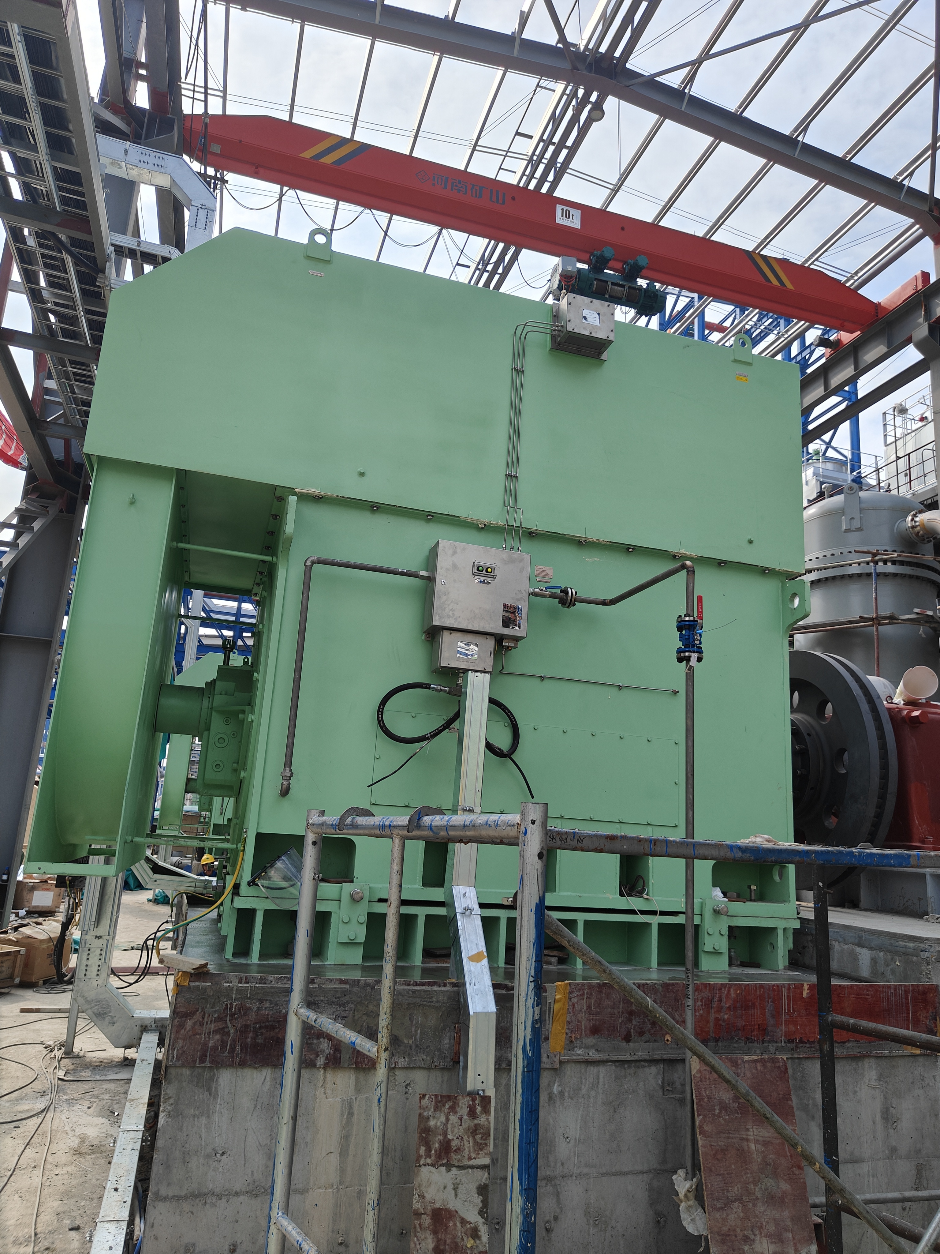
The positive pressure purge control system can not only be used to control the internal ventilation purge pressure of large motors in hazardous places, but also to control the internal ventilation purge pressure of other positive pressure housing type electrical equipment.
The explosion-proof performance of the positive pressure purge control system complies with the requirements of GB/T3836.1 "Explosive gas environment Part 1: General requirements for equipment", GB/T3836.2 "Explosive environment Part 2: Equipment protected by flameproof enclosure "d", GB/3836.3 "Explosive environment Part 3: Equipment protected by increased safety type "e", GB/3836.5 "Electrical equipment for explosive gas environment Part 5: Positive pressure enclosure type "p"".
Explosion-proof mark: Exdb eb[pxb]ⅡCT6 Gb
2. Advantages of Nanyang Huaye Motor's automatic purge device
1. Fast response speed
The scientific gas circuit design of Nanyang Huaye Motor Automatic Purge Device combines the mode amplification and nozzle baffle technology to further expand the low-pressure response performance of the valve. The large ring arc design of the diaphragm greatly improves the sensitivity of the sensor to micro-pressure response, making the system dynamic response performance excellent, leakage compensation response rapid, and follow-up performance agile.
2. Strong stability and high reliability
Relying on the technical strength of the National Pneumatic Laboratory, Nanyang Huaye Instrument boldly innovates the gas circuit design, strives to design concise, reasonable and scientific, and adopts international products such as Bellofram, MAC, and BARTEC in the United States, making the product stable and reliable. It can be said that all product performance indicators have been caught up with or partially exceeded.
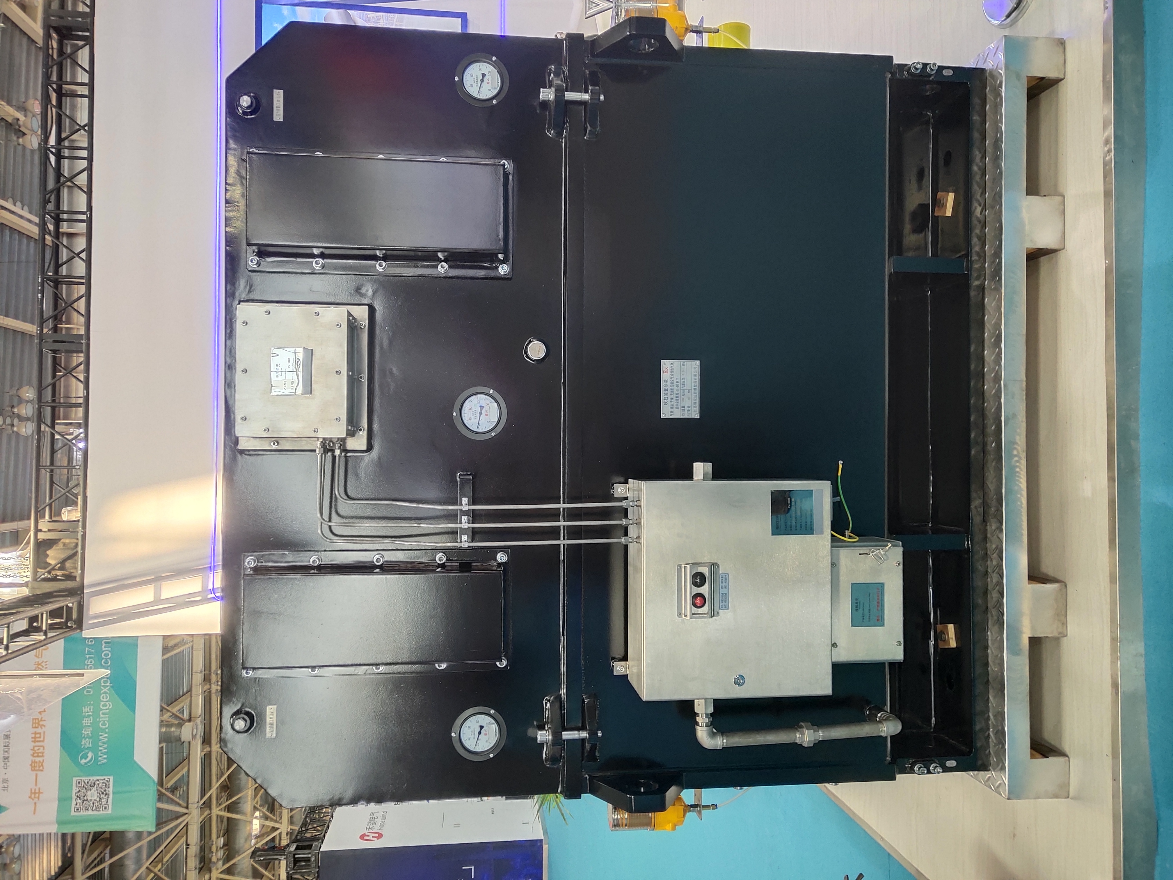
3. System composition
The positive pressure purge control system consists of three parts: a control unit, a wiring unit and a pressure relief unit. The outer shell is made of stainless steel wire drawing process.
4. Product Features
All components of this system are imported international products, which are stable, reliable and durable;
This system is fully pneumatic and automatic, without electronic circuits, and resistant to electromagnetic interference;
The system has fast dynamic response, strong leakage compensation and following ability, and good voltage stabilization effect. When the motor starts, drags the load, and stops, the change in rotor speed will cause the pressure in the shell to fluctuate greatly, and even form negative pressure. This requires the positive pressure control system to have the characteristics of fast dynamic response, strong dynamic following ability of air replenishment, and good voltage stabilization effect, and to provide an opposite effect to the fluctuation at any time, so as to maintain the dynamic stability of the positive pressure in the shell.
5. Model meaning

6. Working Process
The working process of the positive pressure purge control system can be divided into five steps
1) Intake: Open the system's external air source intake valve, and the purge gas enters the electrical housing through the filter and throttle ball valve of the control unit. The air relief valve has not yet opened.
2) Boost pre-purge: As the purge gas continues to enter the electrical housing, an initial internal pressure is formed in the electrical cavity. Through the pressure monitoring point set on the electrical housing, the minimum pressure and intermediate pressure signals detected are fed back to the control unit. The pressure in the cavity exceeds the minimum pressure, the minimum pressure switch is closed, and the air relief valve on the pressure relief unit is opened to start replacing the gas in the cavity for pre-purge. At the same time, the system will send an alarm/boost and intermediate pressure remote transmission signal to the PLC, and the color of the indicator signal on the control unit will change.
3) Start timed purge: The flow of the air relief valve on the pressure relief unit increases with the increase of the pressure in the cavity. At the same time, the pressure monitoring point set on the pressure relief unit transmits the collected signal to the purge flow sensor. The sensor sends a signal to start the timer, and the color of the indicator on the control unit changes.
4) Timed purge completed: When the system set time is reached, the time valve gives a signal, the purge completion valve closes, the air release valve closes, the system sends a linkage signal to the PLC, allowing the motor to start, and the indicator color on the control unit changes.
5) Enter the leakage compensation mode: Through the pressure monitoring point set on the electrical housing, the collected pressure signal is fed back to the system and compared with the set pressure. The result will control the valve core opening and closing degree, thereby controlling the size of the intake volume to compensate for the pressure change caused by leakage and achieve dynamic pressure stabilization.
VII. Main technical indicators
Technical parameters of positive pressure purge control system control unit

Wiring unit technical parameters
Outlet interface: M20×1.5 explosion-proof gland (reference)
Pressure relief unit technical parameters

Selection Guide
When selecting, users should select the purge flow rate based on 5 times the volume of the electrical housing. Generally, the shortest purge time is 20 minutes and the longest is 45 minutes, usually 30 minutes. For example: the volume of an electrical equipment housing is 12000NL, and the purge flow rate is calculated as: 12000NLX5/30min=2000NL/min. It is more appropriate to select 2000 NL/min for the purge orifice flow rate. The definition of electrical housing volume in item 3.5 of GB3836.52004 is the volume of the empty housing without internal equipment. For rotating motors, it refers to the internal net volume plus the volume occupied by the rotor.
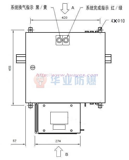
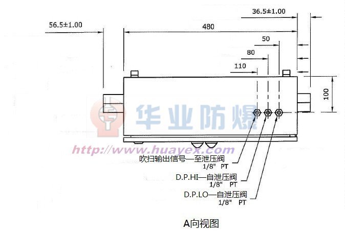
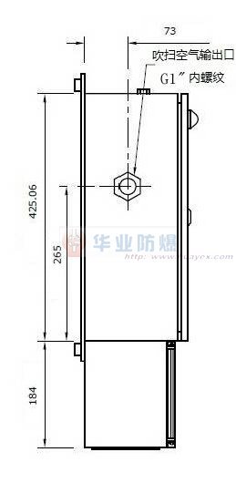
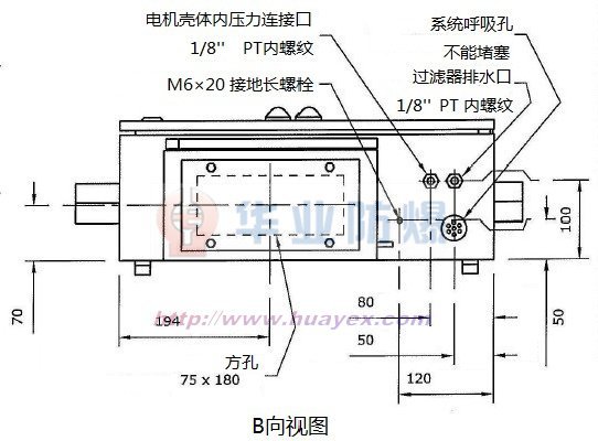
8. Dimensions
Control unit dimensions
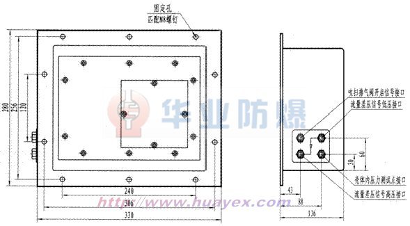
9. Dimensions of pressure relief valve
10. System Installation Diagram

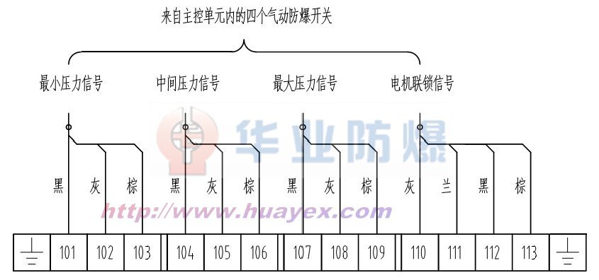
11. Wiring Diagram
12. Installation and debugging
Installation
For the installation of the Pd type positive pressure purge control system, please refer to the system installation diagram. Install a G1″ ball valve as the air inlet valve in front of the air source input port of the purge device for easy debugging. Before connecting the air source inlet of the purge device, open the air inlet valve to blow air to ensure that there are no impurities in the air inlet pipe, and then connect the air inlet pipe. Before turning on the air source switch, check the outlet of the pressure relief valve to ensure smooth flow.
Debugging steps
1. Open the front door of the main control unit, close the purge flow regulating valve (G1″ ball valve), and open the air inlet valve.
2. Check the two pressure gauges in the box. The outlet pressure of the main filter is 5barg, and the outlet pressure of the logic pressure regulating valve is 2.3barg.
3. Check the overpressure action setting of the pressure relief valve: first disconnect the input of the shell pressure test point, slowly open the purge flow control valve, and monitor the pressure in the shell at the same time. When the pressure rises to close to 30mbarg, further slow down the opening speed of the purge flow control valve, closely check the pressure in the box until the pressure relief valve is activated, and record the pressure in the box when it is activated to see if it is close to the set value. If it is close, proceed to the next step.
4. Close the purge flow control valve, wait for the pressure in the shell to disappear, restore the shell pressure to the input of the main control unit, and then slowly open the purge flow control valve. First, you should see that the minimum pressure indicator light turns "green", continue to open it until the purge indicator light turns "yellow", at this time the pressure in the shell should be around 15mbarg, the purge timing time is up, the purge indicator light changes from "yellow" to transparent, the purge ends, and enters the pressure holding state.
5. After the pressure in the shell stabilizes, is it around 10mbarg? If not, adjust the pressure regulating column of the compensation pressure regulating valve until the pressure in the shell is around 10mbarg.
6. The on-site commissioning is completed. The purge device works fully automatically and can be started and stopped by just turning on or off the gas source switch.
XIII. Maintenance
1. Check whether the gas source pressure, flow and cleanliness meet the requirements.
2. Functional inspection of the minimum pressure sensor: The reliability and correctness of the sensor and related pneumatic components are crucial to the safety of the entire device. Regular inspection is required during daily use.
3. Every time the air inlet switch is turned on and the device is started, as the pressure in the shell rises, the minimum pressure sensor triggers the panel indicator light to turn "green" during the rising stage, and a rough judgment is made on its action threshold.
4. The main control single source built-in filter is usually maintenance-free and needs to be checked once a year to clean or replace the core.
5. The fire-blocking net under the pressure relief valve should be checked regularly to ensure smooth flow.
Key words:
Pd series positive pressure purge control system
* Note: Please be sure to fill in the information accurately and keep the communication unblocked. We will get in touch with you as soon as possible.
Nanyang Huaye Explosion Protected Instrument Co., Ltd.
Professional manufacturer of explosion-proof temperature meters and temperature sensors and suppliers of motor supporting instruments
Professional manufacturer of explosion-proof temperature instruments and temperature sensors, as well...
24-hour service hotline
Mobile:+86-15093007079 / +86-13838705322
Address: Middle Section of 3# Road, 2# Industrial Park, High-tech Zone, Nanyang City, Henan Province
E-mail:abc@huayex.com
Fax:+86-377-61613132

Copyright©Nanyang Huaye Explosion Protected Instrument Co., Ltd. This site already supports IPV6 Business License