Welcome to the official website of Nanyang Huaye Explosion-proof Instrument Co., Ltd!
Service Hotline:0377-61613169 | E-mail: abc@huayex.com


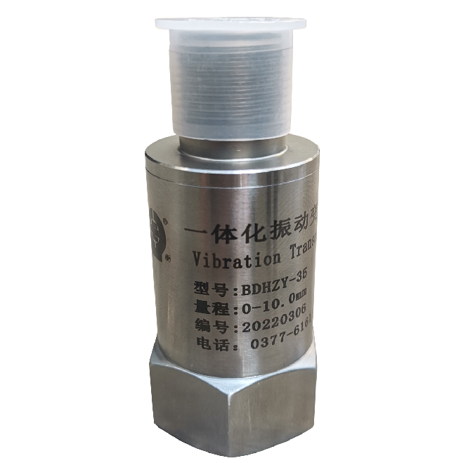
Ordinary integrated vibration transmitter
The integrated vibration transmitter integrates the vibration sensor circuit with the precision measurement circuit, realizes the measurement and transmission function of "sensor + detection instrument", and establishes a high-precision vibration measurement system. It outputs 4-20mA signal and can be directly connected to DCS, PLC or other systems. It is an ideal choice for vibration status monitoring of industrial rotating machinery gears and bearings such as fans, turbines, compressors, and water pumps.
Classification:
Detailed introduction
1. Overview
The integrated vibration transmitter integrates the vibration sensor circuit with the precision measurement circuit, realizes the measurement and transmission function of "sensor + detection instrument", and establishes a high-precision vibration measurement system. It outputs 4-20mA signal and can be directly connected to DCS, PLC or other systems. It is an ideal choice for vibration status monitoring of industrial rotating machinery gears and bearings such as fans, turbines, compressors, and water pumps.
Nanyang Huaye Explosion-proof Instrument Co., Ltd. absorbs advanced technologies in the international vibration sensor industry, mainly including technical parameters of sensitive components, circuit design, special processes, etc., and launches a series of integrated explosion-proof vibration transmitters based on digestion, absorption and innovation. Nanyang Huaye Explosion-proof is committed to providing reliable, stable, and anti-interference vibration monitoring products.
2. Working Environment
Temperature range: -40~+65℃
Relative humidity: 95%
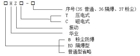
3. Model Description
4. Performance advantages
Low power consumption
Good stability
Can be directly connected to DCS or PLC system
5. Technical indicators
(I) Piezoelectric technical indicators
Explosion-proof mark: EXd‖CT6 Gb or ExtDA21 IP66 T80℃
Protection level: IP66
External power supply: 24VDC±10%
Line polarity reverse protection: signal reverse connection, circuit safety
Input
Signal: taken from piezoelectric system
Frequency response: 3-1000Hz
Input impedance: ≥100KΩ
Range
0-10.0mm/s﹙True effective value﹚
0-20.0mm/s
0-30.0mm/s
0-50.0mm/s
Output
Current output: 4~20mA
Output load: ≤500Ω
(II) Magnetoelectric technical indicators
Explosion-proof mark: EXd‖CT6 Gb or ExtDA21 IP66 T80℃
Protection level: IP66
External power supply: 24VDC±10%
Input
Signal: Signal from built-in speed sensor
Frequency response: 3~1000Hz
Input impedance: ≥100KΩ
Range
Displacement: 0~500um (peak-to-peak value)
Intensity: 0~50mm/s (true effective value)
Output
Current output: 4~20mA
Output load: ≤500Ω
6. Appearance and installation dimensions
Dimensions: Explosion-proof type: Φ36 × 105 mm, ordinary type: Φ36 × 90 mm, piezoelectric ordinary type: Φ26 × 60 mm
Installation dimensions: M10 × 1.5 × 10 mm
Use 2 × 0.3 mm2 shielded cable
7. Structure and working principle
The transmitter consists of a piezoelectric circuit, a signal processing board, a terminal block and a housing. The piezoelectric probe detects the vibration of the object being tested and converts the acceleration of the vibration of the object being tested into a corresponding piezoelectric signal. The signal is processed by the integration and amplification circuit to output a current signal of 4 to 20 mA.
The transmitter is made into a flameproof electrical device according to GB3836.1-2016 and GB3836.2-2016, or a dust explosion-proof type according to GB12476.1-2013 "Electrical Equipment for Combustible Dust Environment Part 1: General Requirements". The explosion-proof mark is Exd‖CT6 Gb or ExtDA21 IP66 T80℃
The maximum surface temperature of the equipment housing does not exceed 80℃.
The flameproof surface of the equipment complies with the provisions of Article 5.3 of GB3836.2.
The cable entry device can withstand the tightening test specified in Appendix A of GB3836.1.
The sealing and mechanical strength of the cable entry device meet the requirements of Appendix C of GB3836.1.
The transmitter has internal grounding and is fixed on the metal equipment housing.
The product has a beautiful and symmetrical appearance.
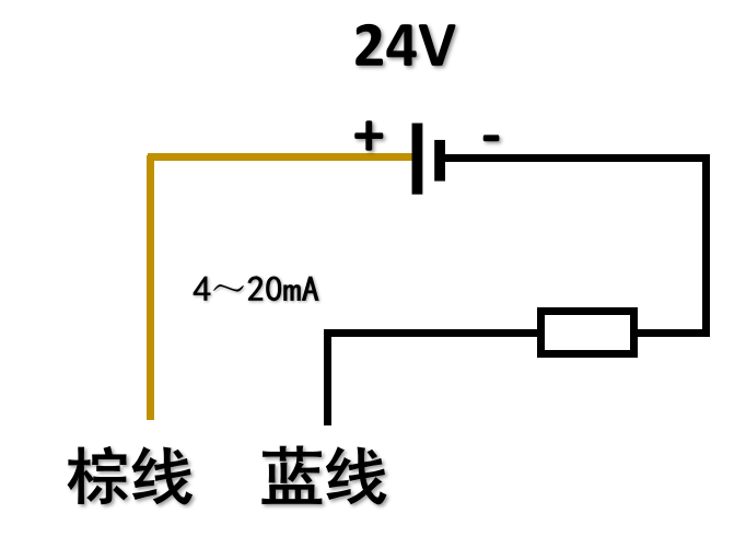
8. Installation and wiring
Correctly install the vibration sensor on the object to be measured. Generally, one end of the stud screw provided by the manufacturer is fixed to the center hole of the transmitter base, and the other end is fixed to the appropriate position of the bearing cover of the rotating machinery. The installation thread is M10×1.5. To eliminate on-site interference, one end of the shielded cable must be grounded.
Wiring identification
Brown line +24V
Blue line 4~20mA output
Shielded line grounding
Key words:
Ordinary integrated vibration transmitter
* Note: Please be sure to fill in the information accurately and keep the communication unblocked. We will get in touch with you as soon as possible.
Nanyang Huaye Explosion Protected Instrument Co., Ltd.
Professional manufacturer of explosion-proof temperature meters and temperature sensors and suppliers of motor supporting instruments
Professional manufacturer of explosion-proof temperature instruments and temperature sensors, as well...
24-hour service hotline
Mobile:+86-15093007079 / +86-13838705322
Address: Middle Section of 3# Road, 2# Industrial Park, High-tech Zone, Nanyang City, Henan Province
E-mail:abc@huayex.com
Fax:+86-377-61613132

Copyright©Nanyang Huaye Explosion Protected Instrument Co., Ltd. This site already supports IPV6 Business License